OT-301DL - Position Sensing Amplifier For Duolateral PSDs
OT-301DL General Description
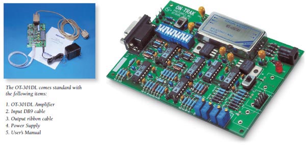
The OT-301DL printed circuit board amplifier is designed for direct integration into OEM instrumentation. Optimized for duolateral Position Sensing Detectors (PSDs) with selectable bias voltages and three gain ranges, the OT-301DL's circuit elements add, subtract and divide detector signals with exceptional accuracy.
Precision op amps and precision resistor networks provide the final ratio. The analog dividers provide the utmost in linearity over a very wide signal range.
The final stages provide +10% reading adjustment of the X and Y outputs and serve as a high-performance output buffer for driving long cables. The sum signal equals the total detector signal and is proportional to the incident beam power.
Features
- X, Y Analog Position Output Voltage
- Sum Output
- Wide Dynamic Range — Three Decades 103V/A, 104V/A, 105V/A
- DC to 15kHz
- Calibration Adjust X, Y
- Zero Offset Adjust X, Y
- Automatic Detector Bias
- Position Independent of Beam Intensity
The OT-301DL includes a DC-DC converter that can be removed and replaced with an external power source for reducing cost in high-volume OEM applications.
Beam position is calculated from the ratio of signals generated by the PSD's two cathode connections (designated X1 and X2) and two anode connections (Y1 and Y2). Four transimpedance amplifiers on the OT-301DL accurately measure all cathode and anode signal currents.
The exact relationship between PSD signals and beam position is as follows:
OT-301DL General Description
The OT-301DL printed circuit board amplifier is designed for direct integration into OEM instrumentation. Optimized for duolateral Position Sensing Detectors (PSDs) with selectable bias voltages and three gain ranges, the OT-301DL's circuit elements add, subtract and divide detector signals with exceptional accuracy.
Precision op amps and precision resistor networks provide the final ratio. The analog dividers provide the utmost in linearity over a very wide signal range.
The final stages provide +10% reading adjustment of the X and Y outputs and serve as a high-performance output buffer for driving long cables. The sum signal equals the total detector signal and is proportional to the incident beam power.
The OT-301DL includes a DC-DC converter that can be removed and replaced with an external power source for reducing cost in high-volume OEM applications.
Beam position is calculated from the ratio of signals generated by the PSD's two cathode connections (designated X1 and X2) and two anode connections (Y1 and Y2). Four transimpedance amplifiers on the OT-301DL accurately measure all cathode and anode signal currents.
The exact relationship between PSD signals and beam position is as follows:
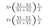
where X, Y is the coordinate of the centroid of the beam spot on the PSD surface
(measured from the detector center); and L is the size of the detector's sensitive surface
in mm (e.g.: 2, 4, 10, 20, 45 mm).
Specifications
Detector Type Duolateral PSD
Input Sensitivity |
-3 | -4 | -5 |
| 10 A/V | 10 A/V | 10 A/V |
X,Y Output Signals 0V to ± 10V
Sum Output Signal 10V max
Calibration Adjust ± 10% of reading
X,Y Zero (offset) ± 1.0V
Bias Voltage 0V or ± 5V
Linearity ± 0.1%
Channel to Channel Tracking 1%
Power AC Adapter ± 12V DC ± 500mA
Size 3.5 x 5.0 inches
Input Connector Receptacle DB9
Output/Power Connector Dual Row 10 PIN Header
Amplifier Gain
| 12 Position DIP Switch | Gain |
| ON = 1,4, 7, 10 | 10-3 A/V |
| ON = 2,5, 8, 11 | 10-4 A/V |
| ON = 3,6, 9, 12 | 10-5 A/V |
PSD INPUT CABLE
| PIN# | FUNCTION |
| 1 | X1 PSD Cathode |
| 2 | X2 PSD Cathode |
| 3 | Y1 PSD Anode |
| 4 | Y2 PSD Anode |
| 5 | GND |
| 6 | NC |
| 7 | NC |
| 8 | NC |
OUTPUT CABLE
| PIN# | FUNCTION |
| 1 | X Position |
| 2 | GND |
| 3 | SUM |
| 4 | GND |
| 5 | Y Position |
| 6 | GND |
| 7 | +/-12V |
| 8 | GND |
| 9 | -12V |
| 10 | NC |