
Laser Alignment & Optical Alignment Tools
Modern optical metrology uses precise lines and planes in space from which measurements are made. Because this method creates these features using light it has become known as optical tooling. the 35 year old historical development and current technology of laser instrumentation as used in optical tooling is discussed in detail. this includes the how the measurements are made, applications, and the technology of alignment lasers and position sensing targets developed for sensing position within a laser beam or plane. the various geometries used to make alignment measurements are discussed in detail. Applications are discussed and the challenges each poses are discussed. the challenge of long range alignment and the effect of the turbulent atmosphere on the measurement process is discussed along with methods of handling the associated errors them.
WHAT IS OPTICAL TOOLING?
Optical tooling is a means establishing and utilizing a line of sight (LOS) to obtain precise reference lines and reference planes from which accurate measurements are made with position sensitive targets. [1] Formerly the measurements were done by a person interpreting a scale or optical micrometer by looking through an alignment telescope; today the lines and planes are created by a laser; the measurements are digital and require no interpretation.
Optical tooling uses the principle that light travels in straight lines to produce precise measurements that cannot be reached by manual or mechanical methods. Level lines can be established over great distances so accurately that every point is exactly perpendicular to the force of gravity. Plumb lines can be set to a given level. Right angles can be produced quickly and precisely with auxiliary components.
In the assembly, maintenance and calibration of industrial equipment or in the alignment of precision systems, one or as many as four basic questions always must be answered: is it straight, is it flat, is it plumb or is it square? A number of techniques have been developed to make these measurements; however, many of them result in inaccuracies so great that proper operation of the equipment involved will be compromised or seriously endangered. the science of optical metrology and alignment makes it possible to achieve the highest degree of accuracy in answering these four important questions. It is no longer necessary to interpret readings or to make constant adjustments and calculations. In laser alignment applications, direct, precision measurements are made rapidly and consistently.
Straightness
In aligning several points, a tight wire is often used as a reference line. this technique has numerous drawbacks and introduces inaccuracy. First of all, wire has weight, which causes it to sag; over long distances this sag can become considerable. In addition, wire vibrates, can bend or kink, and when stretched in the area to be measured, equipment cannot be moved around for fear of disturbing the wire reference line. Even a gentle breeze can cause the wire to move sideways a considerable amount; the aerodynamic drag on a thin wire is huge.
In laser alignment, the LOS of is established by a laser beam instead of a tight wire. the invisible LOS reference has no weight, cannot sag, kink, or be disturbed, nor is it a safety hazard. It constitutes a precise, unvarying reference, determining straightness to within thousandths of an inch.
Flatness
In order to determine flatness a shop level and a straightedge was employed in the past. However, over large horizontal areas, the shop level must be moved from part to part. Consequently, one can only tell the degree of flatness of each individual surface upon which the level is place. Whether all objects in a large area are flat is still in doubt. Flatness over a considerable area must be assured in the erection of large machinery, surface tables and large machine tools. Conventional bubble levels simply do not offer the degree of precision required. "Laser levels", a termed that has fallen into generic use, offer a way to produce a level datum over a wide area. Laser technology has overcome the many disadvantages of bubble levels and assures levelness to within a few thousandths of an inch over hundreds of feet. this high degree of levelness is accomplished by horizontally sweeping the laser beam manually or via a motor driven rotary stage. this revolving line of laser light becomes a horizontal "plane of sight", giving a precise horizontal reference datum, sometimes called a waterline.
Squareness
Perfect squareness implies that one plane forms a 90 degress angle with another intersecting plane. When a steel square is used to test for this condition, the results can be very misleading. Such measurements rely upon the trueness of the steel square, which can vary from square to square with time. In addition, steel squares have a definite limit in their physical dimensions and consequently the testing of very large surface becomes inaccurate, slow and cumbersome. Laser alignment overcomes all these disadvantages and offers a quick and precise method for determining squareness.
One method is to use a transparent penta prism in conjunction with a simple alignment laser. this optical element will split the beam from the laser into two parts; one beam passes through the prism undeviated, the other beam is reflected at a perfect 90 degree angle. this will be described in more detail later. Other systems use three independently mounted lasers that are orthogonal to each other.
Plumb
Classically, a plumb bob is used to establish a single vertical reference line. Of course, as vertical distances increase, the plumb bob becomes cumbersome and inaccurate. It takes a long time for the plumb bob to settle. Also, it can easily be swayed by vibration, air currents, and other disturbances which are bound to be encountered.
In the laser alignment method there are several ways to produce a plumb reference; it can be a plane or a line. To form a plumb line, an alignment laser with autocollimating capability is used with a pool of almost any liquid. Autocollimation senses the angle of an external mirror by reflecting its beam back into the laser head. A position sensor, beamsplitter and lens measure the angle of the reflected beam. When the laser is adjusted such that the internal sensor reads 0 in both axes, then the laser is producing a plumb line. If the laser beam is emitted from a manual or motor driver rotary base whose rotary axis is level, then the swept plane of light is a vertical plane. Position detectors in this plane will give an indication of how far to one side or other they are with respect to the plane.
LASER TOOLING MEthODS
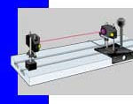
Before lasers and electronic targets came into use, alignment consisted of sighting through two points, near and far, and deciding if an object placed in-between them was to the left or right, or up or down with respect to this LOS. this choosing of two reference points is still the most important selection process of a straightness survey. For example, if a heavy machine tool is being surveyed, the two reference points which determine the LOS should be located off of the machine. If for any reason the machine were to move or deflect all measurements would be in error. the two reference points should be located close enough to be convenient to use and/or out of the way of other people working in the area. transits and alignment telescopes first made these types of measurements. But the problem with transits and telescopes is that they require a person to interpret a scale placed on the object of interest; and usually a second person is holding the scale against the object. It is a two person job that takes time and much training to accomplish successfully. It is also subject to errors. this type of alignment measurement, commonly called straightness, is the most basic of all alignment applications. the figure below shows an alignment laser source on the left whose collimated beam is striking a position sensor target on the right. the target can freely slide and make measurements of straightness of the structure to which it is attached.
Another common requirement is to establish another LOS perpendicular or parallel to the original LOS. To establish a perpendicular a special prism is used: a penta prism. A penta prism has the property that rotation around its axis does not deviate the reflected beam at all; it does not have to be critically mounted. Penta prisms are often called optical squares, an appropriate term. To establish a parallel LOS to an existing LOS typically involves tooling bars if the distance is relatively short, say a meter or less. these bars are made of steel and hold electronic targets at a precise distance from a center. Using two of them with the original LOS establishes a parallel LOS. If the distance between the two LOS is large, then it can be done using the penta prism twice; the first time to turn the beam 90 degrees, followed by a certain distance, and concluded by turning the beam back 90 degrees. Care must be taken that two LOS are truly parallel; usually using a level reference datum makes the task much easier.
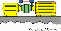
the next alignment application involves measuring the alignment error between two different LOS datums; the typical application is to determine the lateral offset and angular error between two shafts. the shafts essentially define the two LOS's. the measurement consists of setting up the source on one shaft and parallel to it. the targets are placed on the second shaft and surveyed. then the shafts are rotated 180 degrees and surveyed again; the difference is twice the shaft offset. If the target is placed at two axial locations and measured for offset, the difference in the offsets divided by twice the axial separation is the angular error in radians. the figure below shows a typical method to measure shaft alignment errors using a laser and target.
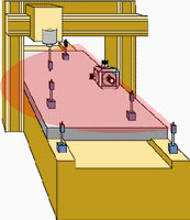
A more sophisticated alignment application is to sweep a laser beam quickly to generate a plane of light. the advantage of this is that many targets can be aligned using one laser source. In simple straightness applications the target location is restricted to the active area of the position sensor. In swept plane alignment, the targets are using sensitive in only one dimension. A typical application to establish a level plane is to put three or more targets at the same (desired) waterline location and adjust the structure the targets are on until all targets read the same. the targets for swept plane alignment can be static, meaning they require the laser beam to be directed in to them constantly. Usually the laser beam is swept by hand by rotating a knob on the laser source. If the laser plane is moving at high speed, say once a second or faster, then the targets must capture and hold the position of the laser beam as the beam sweeps by. the problem becomes harder to accomplish at longer distance because the beam is on the detector for such a short periods of time. the figure below shows a horizontally swept level laser beam scanning by several targets placed on a machine bed. By moving the targets around high and low spots can be discovered and measured.
REVIEW OF LASER ALIGNMENT TECHNOLOGY
In 1961 shortly after the invention of the helium-neon (HeNe) laser by Javan [2] the first alignment laser systems appeared. the HeNe laser was the first practical way to produce continuous wave (CW) light. Up until then a CW laser had been termed an invention looking for an application. the high degree of coherence and Gaussian intensity profile allowed it to be easily collimated, or formed into a beam that could propagate a long distance without much spreading. Usually the 1 mm diameter of the HeNe laser was expanded to 6 to 12 mm to provide for good collimation over a reasonable range. the physics of propagating laser beams dictate that the larger the initial diameter of the beam then the less it will spread. the alignment system was simple in concept; since light travels in a straight line, position sensitive targets which can intercept the laser beam at various places along the path of the beam will provide a straightness measurement.
Alignment Targets
the first 2D (two dimensional) position sensitive targets initially consisted of four square photodetectors grouped together in a 2 x 2 arrangement; it was termed a quadcell. [4] Laser beam position on the surface of this target was computed with analog signal processing. the most basic method simply measured when the beam exactly straddled the boundary between two photodetectors. this nulling method was very repeatable and it had the same accuracy independent of the power of the laser beam. this method does can not give meaningful data when the laser beam is displaced from its nulled position.
the first position sensitive targets which measured displacement appeared in the early 1970's. It used the difference in the outputs of two photocells opposite each other. this method was accurate to about 1/8 of a laser beam diameter. Measurement beyond this distance caused the difference (displacement) signal to decrease in value, finally reaching a final value when the laser beam was completely on one photocell. In fact, with a quad-cell (or bi-cell target for 1D applications) it is never possible to measure any farther than 1/2 of abeam diameter from side to side. Another major drawback in this method is the measurement is proportional to laser power. Variations in power received on the detector due to atmospheric attenuation, laser warm-up, power supply or temperature required manual adjustment of signal gain. the interim solution was to frequently check the displacement a target was producing with a field checking fixture. this was nothing more than a cylinder which slipped over the front of a target. the fixture contained a 1/4 inch thick glass window tipped at a small but precise angle. this produced a known lateral displacement of the laser beam at the surface of the target. If the measurement was too large or small, a pot was adjusted to return the measurement to its correct value.
the next development in the mid-1970’s was to improve the signal processing and produce a displacement signal that was independent of laser beam power. this was done using an integrated circuit called an analog divider. Analog dividers formerly were large, rack mounted instruments which, with the advent of microelectronics, had been drastically reduced in size and cost to a single integrated circuit. the measurement signal was computed by dividing the difference of the two photocell outputs by their sum. Since both the difference signal and the sum signal are proportional to laser power, dividing one by the other results in a ratiometric signal that did not depend on incident laser power; it truly measured laser beam position on the target.
However, there remained many disadvantages. Significant ones still was a nonlinear measurement, a linear measurement range restricted to about 1/8 of a beam diameter, and sensitivity to ambient light. Ambient light could be occluded by the use of tubes placed over the ends of targets or by using interference filters which rejected any light not of the laser's wavelength. But these filters are expensive and tubes are cumbersome.
the effect of ambient light or shadows cast on the surface of the detector could be rejected if the laser was amplitude modulated. But modulating a HeNe laser is particularly difficult because of the 1000 volts required to keep the plasma tube excited. Practically, only a 10% modulation depth is achievable on a HeNe laser. this essentially cuts down on the useful signal level by a factor of 10 because the static or DC level of the laser is rejected by the processing circuitry.
the advent of the Position Sensing Detector (PSD), or Walmark photodiode in the late 1970’s allowed for larger and more linear measurement ranges. the PSD is a planar piece of doped silicon which produces a signal that is proportional to the intensity and the position of the "center of intensity" of the light falling on it. Unlike a quad cell the PSD does not range saturate when the light spot has moved more than 1/2 beam diameter. the PSD produces a monotonically increasing signal as the light spot moves across its surface. the PSD does not distinguish structure that is; it is not an imaging sensor. It will produce the same signal if a small diameter laser beam of a given power strikes it as well as the same power spread out in a large diameter. this is usually not a problem. One advantage of the PSD is that it is very fast compared to photocells; some have an upper frequency limit of a megahertz. the typical PSD was termed a tetralateral type as it had 4 electrodes and a ground return path. these PSD types still exhibited some linearity errors at measuring ranges farther than 25% of its active diameter. Today there are duo-lateral types with shaped electrodes on the planar surface that give a very linear signal.
Some targets use CCD (charge coupled array) detectors. CCD targets use the came type of detector as used in video cameras. these targets are much more expensive and slower than PSD types. they have one big advantage; since they can sense structured light they can determine the centroid of a beam even in the presence of noise or a non-circular beam. they do this by using digital signal processing (DSP) techniques. that is why these type of targets are more expensive; the signal processing required is actually image processing which is computationally time intensive. However, as the price of CCDs and DSPs come down and their speed goes up, more and more targets will use CCD array as their optical position sensors.
Microprocessors appeared in the early 1980’s and allowed greater flexibility and processing of signals. Now a system could be almost entirely digital in nature. this allowed them to be connected to networks and send their data over great distances. A PSD could be corrected for its errors by calibrating it during manufacture and storing the errors in a software look up table or by using curve fitting routines. When a measurement is made the LUT or curve fitting routine adjusts the raw data from the PSD into a very accurate displacement signal. One huge advantage with this technique is that it allows all targets to be metrologically identical independent of the particular PSD used. the lookup table can be stored in a memory chip right in the target, next to the PSD. Usually this is done with a non-volatile memory component such as an electrically erasable read-only memory. Finally, the duolateral PSD appeared in the late 1980's which essentially provided better than 0.1% linearity across the whole detector surface.Laser Sources
As mentioned previously, the first sources of laser light were HeNe lasers. At the beginning they had a very short life; usually less than 1000 hours. Eventually their lifetime was increased by perfecting the glass-metal seals of the plasma tube. One bad characteristic of HeNe's is their efficiency; less than 0.1%. Virtually all of the 5W or so of power required for a 5 milliwatt laser appear as heat. One critical design characteristic for an alignment system is the pointing error of the laser. For gas lasers such as the HeNe, the direction the laser points at startup is not going to be what it points to after 1 hour. Typical drift rates are 0.1 to 1 milliradian per hour; maximum drift can be as large as 10 milliradians. this amount of pointing error would cause a 1 inch shift at 8 feet! Plasma tube type lasers such as the HeNe are notoriously bad for pointing stability. Even after they have warmed up, a gentle breeze across its case will cause the laser beam to steer in a different direction. this type of error always causes errors in measurement unless the operator: a) can make the measurements in less time than the drift occurs or b) re-aims the laser at a known reference point frequently.
In the early 1990's the first visible laser diodes made an entrance for use as a collimated source. they are small, low cost, require very little power, have efficiencies of 5 to 10% and vanishingly small drift rates. Optically, however, they are inferior to gas lasers. the light from a typical laser diode is emitted from a small rectangular aperture about 1 x 3 microns in size. Because of this small aperture the light diffracts, or spreads strongly with distance; it also has two different spreading angles because the aperture is rectangular. If a good quality lens is placed such that its back focal length coincides with the laser diode emitting surface, the beam produced will be elliptical in cross section and suffer from astigmatism. the astigmatism is a consequence of the aperture and results in a beam that always has two waists instead of one.
Much effort is required to transform the light from a laser diode into a high quality collimated beam appropriate for use in precision alignment systems. the PSD detectors works best with a beam of circular cross section and that has one waist. three approaches are used to improve the quality of a collimated beam from a laser diode; internal and external cylindrical optics; external prism optics and fiber coupling.
the cylindrical lens is used to make the diffracted light emerging from the laser diode to have the same diverging angles in both axes. It is now possible to buy a laser diode with this lens inside the typical 9 mm diameter by 5 mm long laser diode case. Unless this lens is chosen carefully there still can be significant astigmatism is the optical system. External prism pairs can be used to circularize the laser beam, but it does not solve the astigmatism problem.
the best way found to date that lets a laser diode have most of the same properties as a HeNe laser is to couple the light from a laser diode into a single mode optical fiber. this is usually done inside a small package that integrates the laser diode with a pair of aspheric lenses that efficiently couples the light into the fiber. the light emerging from the other end of the fiber is of uniform cross section, has no astigmatism, and has a well defined diffraction angle. the fiber end is then placed at the back focal length of a lens. the collimated beam produced is nearly the same as that produced by a HeNe laser. By choosing different focal length lenses the laser beam can be of any diameter desired. the drift rates of these laser sources are caused not by the laser, but by the package in which it is enclosed. If a steel case is used, maximum drift can be as low at a few arc-seconds.
the light from a laser diode is polarized in one plane. the fiber coupling method does introduce a random polarization to the beam after it has traveled through the fiber. Randomly polarized light is usually not a problem for an alignment target consisting of a lateral effect photodiode.
Mechanical Tooling
In all laser measurement applications a question always arises as to how to mount the targets and laser sources. Usually commercial equipment vendors will supply their own proprietary mounting hardware. there is only one non-proprietary optical tooling standard for precise positioning of targets and lasers. It is called the National Aerospace Standard (NAS) and is based on all components fitting into precision 2.25 inch diameter bores. the NAS mechanical interface is used for locating and mounting of all optical tooling instruments. this universal mounting system consists of a tooling sphere and a 3 point cup mount. the tooling sphere is a truncated 3.5 inch diameter steel sphere. these sphere are 2 inches thick and have a 2.25 inch diameter bore machined precisely though the center of the sphere. the optical target, or laser source is inserted into the bore of the sphere and then the sphere is mounted onto a three point mount and clamped. the targets are designed such that the optical sensors sit exactly at the center of the sphere. If the target is tipped slightly then the reading doesn’t change. Figure x below shows a transparent Target and reference target using these tooling spheres.
SINGLE TARGET LASER ALIGNMENT
the main disadvantage of early alignment laser systems is that they only employed a single target. A target placed at a reference station establishes one end of the LOS; the center of the laser beam is the other end of the LOS. the laser source is first carefully aimed at the center of the target. then the operator moves the target from its reference position to use it at intermediate locations.
there are two significant problems with single target laser alignment:
- the operator is unaware of any movement of the laser beam; and
- alignment errors are introduced unless laser position at Reference is frequently checked
the only way to check for beam movement is to stop alignment operations, remove the target from its working location and move it to the reference station position. the position of the laser beam on the target at the reference station is then checked, and the laser beam re-aimed if necessary. this method is only useful for slow variations in laser beam position at the reference station caused by thermal disturbances in the structure being aligned, or in geologic influences at the laser source location. High frequency disturbances such as vibration can not be corrected.
TWO TARGET LASER ALIGNMENT
If two targets are used the measurement becomes more accurate; the addition of a Reference target situated at the end of the LOS constantly monitors beam position. the target used by the operator to allow passage of light to the Reference target is termed the Alignment or transparent Target.
Passive Pointing Compensation
If the two dimensional coordinates of the laser beam on the Reference and Alignment target are measured simultaneously the position of the Alignment target with respect to a line between the laser and the Reference target can be measured, independent of any pointing error of the laser. the laser beam need not be precisely aimed onto the center of the Reference target. Instead, the coordinates of the laser beam at both targets is used to compensate for any laser beam movement.
In Figure x the line between the center of the Reference target and the center of the laser beam source defines the LOS, not the laser beam. the laser beam is shown directed upward, representing a laser pointing error. the transparent Alignment Target is shown centered with respect to the LOS. the pointing or wedge error as measured at the Reference (R) target is h. Because of similar triangles the pointing error is h’ or (d/D)*h at the Alignment target. Subtracting this error from the measured beam position at the Alignment target results in a compensated (C) alignment measurement, or true position of the target in both the x and y axes:
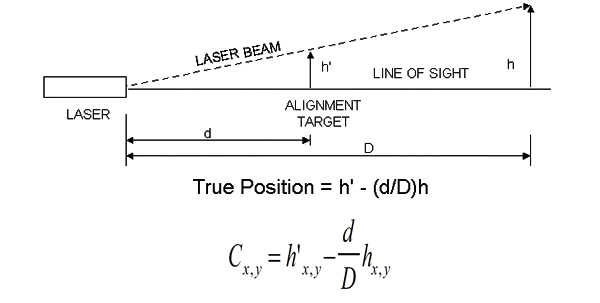
the LOS is defined by two points: one point being the center of the laser case and the other being the center of the Reference Target. the constants d and D are measured in the field or have been previously entered into the computer. Absolute target distances are required. Because of how this technique uses geometric principles, it is called similar triangle compensation or passive pointing compensation.
Active Pointing Compensation
Perhaps the most recent method to compensate for steering of the laser beam due to thermal, mechanical or atmospheric effects is to actively steer the laser. this technique uses all of the components as passive pointing compensation except the laser is now fitted with internal or external pitch and yaw pointing actuators. the distant Reference Target sends its error signals back to the laser where steering occurs to null out the error; the system acts as an optical servo. One advantage of this method over that of the similar triangle method is that absolute or ratiometric distances are not needed. Since the laser is always on the Reference Target center, no mathematical compensation needs to be applied. Any transparent Target placed in the beam at any distance from the laser simply determines beam position. In this method the laser beam is the LOS.
SCANNING SYSTEMS
Scanning systems can be simple single axis systems that are manually rotated, or have 3 axes with each axis motor driven. the simplest laser sources for these types of system are small boxes with leveling feet and bubble vials. the user must set up the source to a level condition before it can be used. For three axis systems, once level has been established the other two axes will sweep out vertical planes of light that are perpendicular to each other. the most sophisticated scanning sources sweep out the beam automatically via a motor and they also contain internal level sensors. Some even control the degree of "levelness" by servo correcting the source if it moves off of level. A simpler method uses a pendulum on which a light weight laser diode source is attached.
the targets for these types of sources are always one dimensional. For a manually rotated source the electronics are similar to 2D targets; the user must aim the beam by hand into the target's window. For dynamic scanning the targets use very fast detector as the beam sweeps by in only a few microseconds if the target is located at some distance and the scan rate is 60 RPMs or higher. Sometimes PSDs are used as the sensor. For very high speed systems a bi-cell sensor is used. the sensor is rectangular and oriented in its long direction. A typical size would be 30 mm tall by 5 mm wide. But this sensor is split along its diagonal into two triangular shaped photodetectors. the two triangular shaped parts of the bi-cell are each connected to a timing circuit. When the time the laser beam spends on each segment is equal, the beam is exactly in the middle of the bi-cell. Deviations up are down produce a difference in timing that is exactly proportional to distance.
the main advantage of scanning systems is that many targets can be placed in the scan zone. It has a 360 degree scanning window and is really designed for leveling applications. Accuracy is the same as for simple laser alignment and will be discussed in detail later.
ERROR SOURCES
Any laser alignment system has associated with it measurement errors. Even if active and passive pointing compensation is not employed, any transparent Target must not produce steering or deviation of the laser beam as it passes through it. the system’s accuracy depends on the laser beam traveling in a straight line from the laser, through (possibly several) transparent Target(s) and finally to the Reference Target. the transparent Target will usually use some sort of a beam splitter and have windows on each end of it. Each window and the beam splitter possess a small amount of wedge error which acts to mis-steer the beam. though the wedge error of these components is usually small (tens of arcseconds) at long distances the displacement errors can become large. there are two types of errors which can be injected into the compensation equation; that due to steering of the laser beam by the transparent Target (wedge angle error) and that due to the target being slightly tipped (deviation error).
Wedge Angle Error
Rotation adjustment of the wedge prisms on the transparent Target allows for the refractive error of the transparent Target to be adjusted to less than one arcsecond. Figure 3 shows a two target system with the laser beam initially centered on the Alignment target.
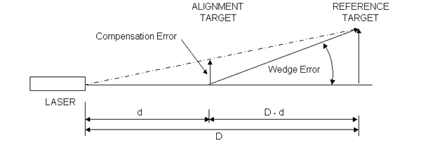
the Alignment target is shown with a wedge error of δ and it steers the incident laser beam away from the LOS. the laser beam strikes the surface of the Reference target at a distance of (D-d)δ from its center. the compensation algorithm then produces an error, ε, of magnitude:
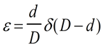
due to the wedge error δ of the transparent alignment target. Inspection shows this error is zero when the alignment target is situated at a distance of 0 or D from the laser source. If the alignment target was situated next to the Reference target (d=D) it would impart no significant steering error at the Reference Target. If it were located next to the laser (d=0) the wedge error as seen at the Alignment target is also zero. the error is greatest when the Alignment target is located halfway between the laser and Reference target.
table 1 below shows how transparent Target wedge error affects system alignment accuracy as a function of laser to Reference Target distance, D. the table assumes the alignment target is situated at D/2; or half the laser to Reference Target distance.
| Distance | Distance | Distance | |
|---|---|---|---|
| Wedge δ | 50 feet (15.25 m) | 100 feet (30.5 m) | 300 feet (91.5 m) |
| 10 arcsec | 0.0075 in. (190) | 0.015 in (380) | 0.045 in. (1140) |
| 1 arcsec | 0.00075 in. (19) | 0.0015 in (38) | 0.0045 in. (114) |
| 0.5 arcsec | 0.00037 in (11) | 0.00075 in. (19) | 0.0022 in. (57) |
[Inches (Microns)]
Target Deviation
Another error is made due to tipping of the target due to the deviation of the laser beam as it passes through the windows and/or beam splitter. Deviation errors do not grow with distance as do pointing errors. table 2 below indicates the magnitude of error due to target tipping in yaw or pitch for a total glass thickness of 8 mm. this thickness represents the thickness of the windows and beamsplitter in a transparent Target.
| Tipping Angle | Error |
|---|---|
| 1 degree | 0.0018 in. (46) |
| 3 degrees | 0.0054 in. (138) |
[Inches (Microns)]
Target Accuracy
Most modern position sensitive targets used in alignment contain dedicated microprocessors. they can communicate their data over a bus or through the air with optical data links. the electronics of each target usually consist of a microprocessor; non-volatile, electrically erasable programmable memory (EEPROM); analog-to-digital converters; filters and serial communication drivers. Targets come in a variety of different sensing areas and virtually all use lateral photodiode detectors to sense laser beam position. Quad-cells are almost never used due to their small sensing range. Since each lateral photodiode detector has slightly different linearity, manufacturers now calibrate each target on a precision motion platform. Stored within each target are corrections for its detector. the result is that all targets are metrologically identical. A good rule of thumb for target accuracy is 1 part in 500 of a target's sensor diameter. For example, a target with a PSD sensor diameter of 1 inch would have a position accuracy of +/- 0.002 inches. Scanning type targets have similar accuracies. Much effort has been expended on describing how to make and interpret optical measurements and how such statistics as standard deviation is defined for an area target. [5]
APPLICATION AREAS
For simple straightness applications a non-compensated laser alignment system is adequate. For situations where high accuracy is required, active pointing compensation is ideal. Active pointing compensation of the alignment laser eliminates movement of the laser beam by maintaining precise alignment of the laser beam on the reference target.
Some applications areas include:
- Wing and fuselage alignment
- Particle accelerator component alignment
- Steam turbine alignment
- Extruder alignment
- Hinge alignment
- Bore alignment
- Guide rail alignment
- Periscope alignment
- Antenna alignment
- Steam catapult alignment
- Propeller shaft alignment
- Machine tool alignment
LASER BEAM PROPAGATION
A propagating laser beam does not remain parallel as is frequently assumed. Even with “perfect” projection optics the laser beam obeys the laws of physics; the dominant law here is diffraction. All laser beams follow a prescribed propagation characteristic that depends on two conditions: how the beam was launched, and what type of disturbed it encounters along it path. the first is greatly controllable; the second is usually not.
Laser Beam Launch Conditions
Parameters
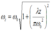
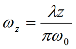
the only two parameters which govern how a laser beam behaves after it is launched are: initial diameter and wavelength. [6] For a given wavelength, the larger the initial diameter the less the beam will spread with distance. For a given distance, a laser beam with a long wavelength will grow in diameter faster than a laser beam of a shorter wavelength. these propagation characteristics are embedded in the exact equation below which is a result of electromagnetic theory.
| Initial Diameter | Depth of Field (m) | Depth of Field (feet) |
|---|---|---|
| 1 mm | 1.2 | 4 |
| 4 mm | 20 | 64 |
| 10 mm | 123 | 403 |
| 20 mm | 492 | 1614 |
| 25 mm | 769 | 2522 |
Atmospheric Conditions
A beam of light propagating in a vacuum obeys the laws of diffraction and is not affected by any other source. the index of refraction for a vacuum is defined as exactly equal to one (1). However, in an atmosphere the beam will behave differently. the index of refraction of air being slightly larger than one causes changes in the propagation characteristics of a light beam. the two dominant effects on the beam are to make it move or quiver, and the other is commonly called scintillation which means the intensity of the light beam varies as a function of time.
Much work has been conducted on the effects of atmospheric turbulence on propagating light. the index of refraction of air being different along the path length causes these two effects. the index of refraction of air is strongly affected by temperature, and to a lesser extent pressure and water vapor pressure (humidity). An expression for the index of refraction due to temperature, pressure and humidity is given by:
where T is in degrees Kelvin (Ko= Co + 273), P and H are in millibars. It can be appreciated that it is a weak effect by the 10-6 factor in front of the second term. For most applications the expression is simplified, keeping pressure at a normal 1013 millibars and ignoring humidity.
Perhaps the best known treatise on how the atmosphere affects light and sound propagation was by Tatarskii, [7]. He identified how wind velocity affects scintillation, and what the power spectral density was of the scintillations. He also determined how random side to side motions scaled with distance and how propagation was affected by different atmospheric conditions. Measurements were made for all regions of the atmosphere, from the ground, through the troposphere and into the stratosphere. Most of the measurements involved the frequency of the scintillations and not the positional shift of the light beam. Precision optical displacement devices and even lasers were not available when most of the measurements were made in the mid-1940’s and early 1950’s.
Perhaps the most important contribution made was the introduction of atmospheric structure constants. these parameters provided information as to how turbulent the atmosphere was. One of these important constants was the correlation distance.
Correlation Distance
this is lateral distance from a propagating beam of light under which the scintillation and turbulence would be completely different for a neighboring beam. For a quiet atmosphere where there is gentle and thorough mixing of the layers the correlation distance ρ is equal to [8]:
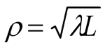
where λ is the wavelength of the light and L is the distance from the source. the correlation distance is important because it affects the choice of beam diameter. For example, if a range of L = 123 meters is used (from the depth of field table for a 10 mm diameter beam), then for a λ of 0.635 microns (0.635 x 10⁻⁶ m) the correlation distance is 8 mm. What this means is that since the laser beam diameter required for good collimation is approximately the same size as the correlation distance, the beam will undergo slight amount of fading. the fading is due to one side of the beam interfering with the other side after traveling a long distance and experiencing a different atmosphere. If the beam were than the correlation distance this effect would not happen. Indeed, experience has shown in the field that on "long shots" if one holds a piece of paper up to beam at a long distance from the source, the spot on the paper will change shape quickly. It will be circular one moment and highly elliptical the other. A non-circular beam will cause errors in laser beam position measurement as PSD targets measure the centroid of the laser beam.
Remedies
there are a few ways to remedy these effects. One is to make certain that there is no cross beam wind component. this can be achieved with tubes enclosing the beam path. Another method is to blow air down the laser beam path with fans. the idea is to eliminate cross beam wind components with down beam velocity component. If air conditions used in the building it should be turned off as the extremely cold air mixing with hot air gives rise to the worst beam deflections possible.
Some other remedies are to change the range or the wavelength used. For example, decreasing the range to 50 meters would decrease the correlation distance to 5.6 mm. If a blue wavelength laser were used with a λ of 0.42 microns the correlation distance would be about 6.4 mm at 123 meter. the basic consideration in long distance shots is to have the beam diameter as small as or smaller than the correlation distance.
the highest expected frequency of scintillations is:
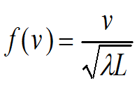
where ν the cross-beam velocity component of the wind. It should be noted that L in this equation and the above one can not take on any value; L must be located in the far field of the source; usually this is a distance on the order of 10 meters. For the same situation as above with L = 123 meters, λ of 0.635 microns and a 1 meter/sec velocity the maximum frequency of beam scintillation is 113 Hz. As in any data acquisition system, if one samples laser beam position at the target at least twice this frequency, aliasing errors will not occur.
CONCLUSION
Modern laser alignment technology has been described. Applications of the four basic optical tooling set-ups; straightness, plumb, flatness and squarenss have also been discussed. the tools of laser alignment, the laser, and the targets have been discussed in detail.
Typical accuracies and error sources were listed. Finally, the problem of a turbulent atmosphere was discussed along with some means to reduce its effects on a propagating laser beam
REFERENCES
- D C Williams, Optical Methods of Engineering Metrology (ISBN 0-412-39640-8) 477 pp Charles S Williams, Orville A. Becklund (1989)
- U.S Patent 594,349, 1961
- J. D. trolinger, Optical Inspection and Testing (ISBN 00-8194-1039-X) 284 pp/11 papers
- Handbook of Optics, Discol, W., Ed., McGraw Hill, 1978
- Lionel R Baker, Specification and Measurement of Optical Systems (ISBN 0-8194-0960-X) 250 pp/36 papers
- Introduction to the Optical transfer Function, Wiley-Interscience (ISBN: 0-471-94770-9) Yoder (1986) Opto-Mechanical System Design, New York, Dekker
- Tatarskii, V. I., “the Effects of the Turbulent Atmosphere on Wave Propagation”, Moscow, 1959
- Smith, F. “the Infrared and Electro-Optical Systems Handbook” Vol. 2, Atmospheric Propagation of Radiation, SPIE Press, 1993