The OT-301SL - Position Sensing Amplifier For Single Axis PSD
OT-301SL General Description
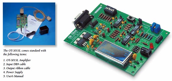
The OT-301SL printed circuit board amplifier is designed for direct integration into OEM instrumentation. Optimized for single-axis Position Sensing Detectors (PSDs) with selectable bias voltages and three gain ranges, the OT-301SL's circuit elements add, subtract and divide signals with exceptional accuracy.
Precision op amps and resistor networks perform addition and subtraction operations; optimized analog dividers provide the final ratio. The analog divider ensures the utmost in linearity over a very wide signal range.
Features
- Analog Position Output Voltage
- Sum Output
- Wide Dynamic Range - Three Decades 103V/A, 104V/A, 105V/A
- DC to 15kHz
- Calibration Adjust
- Zero Offset Adjust
- Automatic Detector Bias
- Position Independent of Beam Intensity
The final stages provide ±10% reading adjustment of the position output and serve as a high performance output buffer for driving long cables. The sum signal equals the total detector signal and is proportional to the incident beam power.
The OT-301SL includes a DC-DC converter that can be removed and replaced with an external power source for reducing cost in high-volume OEM applications.
Beam position is calculated from the ratios of signals generated by the PSD's two anode connections (designated Y1 and Y2). Dual transimpedance amplifiers on the OT-301SL accurately measure the PSD's anode signal currents. The exact relationship between PSD signal and beam position is as follows: the total detector signal and is proportional to the incident beam power.
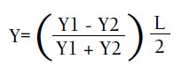
where Y is the coordinate of the centroid of the beam spot on the PSD surface (measured from the detector center); and L is the size of the detector's sensitive surface in mm (e.g.: 2.5, 5.0, 10, 20, 30 mm).
Specifications
Detector Type Single Axis Position Sensing Detectors
Anode Outputs (Common Cathode)
Cathode Outputs (Common Anode)
Bi-Cell (Common Anode or Cathode)
Input Sensitivity |
-3 | -4 | -5 |
| 10 A/V | 10 A/V | 10 A/V |
Y Output Signal 0V to ± 10V
Sum Output Signal 10V max
Calibration Adjust ± 10% of reading
Y Zero (offset) ± 1.0V
Bias Voltage 0V, ± 5V, or ± 12V
Linearity ± 0.1%
Chanel to chanel tracking 1%
Power AC Adapter ± 12V DC @ 500mA
Size 3.5 x 5.0 inches
Input Connector Receptacle DB9
Output/Power Connector Dual Row 10 PIN Header
Amplifier Gain
| 6 Position DIP Switch | Gain |
| ON = 1,4 | 10-3 A/V |
| ON = 2,5 | 10-4 A/V |
| ON = 3,6 | 10-5 A/V |
PSD INPUT CABLE
| PIN# | FUNCTION |
| 1 | Y1 PSD Anode |
| 2 | Y2 PSD Anode |
| 3 | N/C |
| 4 | N/C |
| 5 | GND |
| 6 | NC |
| 7 | NC |
| 8 | PSD BIAS |
| 9 | GND |
POSITION OUTPUT/POWER INPUT
| PIN# | FUNCTION |
| 1 | Y pos |
| 2 | GND |
| 3 | SUM |
| 4 | GND |
| 5 | N/C |
| 6 | GND |
| 7 | +12V |
| 8 | GND |
| 9 | -12V |
| 10 | GND |