The OT-7000. Auto-Centering, Wireless, Multi-Target Alignment.

OT-7000 Alignment Laser System

Now, the most powerful way to measure alignment at distances up to 300 feet is more convenient and flexible than ever. On-Trak Photonics' OT-7000 Laser Alignment System provides an autocentering and wireless solution for performing real-time measurement of multiple targets along a single reference laser line.

Dynamically monitor work as it progresses. The OT-7000 displays X-Y deviation of each measurement target simultaneously-over your Windows based computer, at the RF controller module, or via LED displays located on each target's dedicated CPU.

Used by leading aircraft manufacturers, shipbuilders and the automotive industry, On-Trak Laser Alignment technology is proven to streamline efficiency and significantly reduce man hours. The OT-7000, with its auto-align and wireless capability, will only boost this productivity further.

Auto-Alignment Capability.

Loading stress and thermal changes during the manufacturing process can cause conventional alignment systems to move out of center on the reference target. The OT-7000 compensates for this with an automatic feedback loop that constantly monitors and re-centers the laser via internal motion controllers. User-programmable settings enable you to adjust centering sensitivity levels and feedback sampling rates. Store these values into memory for future recall.

Auto Alignment

Multi-Target, Wireless Communication.

No more cabling hassles-tangling, storage, damage, routing headaches, etc. The OT-7000's wireless design makes it easy to instantly add or remove measurement targets anywhere along the laser line. RF spread-spectrum technology (902-928 MHz) provides rock-solid wireless communications between key components.

Advanced Computer Control.

Collect and process measurement data with your Windows-based computer. Beam-Trak 7000 software displays X-Y deviation of all targets, enabling you to dynamically monitor work in progress. 0.001-Inch Resolution At 300 Feet. Optimize precision and gain a greater measure of confidence. The OT-7000 provides 0.001-inch resolution at distances up to 300 feet. A third generation fiber-coupled laser diode delivery system ensures exceptional beam quality over long distances.

Laser Alignment At A Glance

ot7000-b

How Laser Alignment Works.

The principle of linear laser alignment is simple. A stationary laser, aimed at a reference target up to 300 feet away, creates a "line in space" that serves as a rock-solid measurement reference. Next, one or more transparent targets are placed directly in the beam path. As the laser light passes through each transparent target, the target is able to determine the X-Y deviation of the laser beam with respect to the center of the tooling sphere. X-Y data gathered from each target is displayed on its dedicated CPU. This information is simultaneously transmitted wirelessly to the RF Controller Module. Measurement data is then collected and displayed on a desktop or laptop computer.

The Line Laser Advantage.

Laser based alignment provides significant advantages over competing alignment techniques.

  • Cost Effective. Outperforms laser tracking systems in this specific application, at a fraction of the price.
  • Ultra Precise. Eliminates margin of error associated with subjective manual approaches.
  • Real-Time Feedback. Enables user to make on-the-spot alignment adjustments.
  • Faster Measurement. Reduces man hours and facilitates project efficiency.
  • Maximizes Range. Perform measurements at distances up to 300 feet.
  • Simultaneous Measurement. Enables simultaneous measurement from multiple targets.
  • Data Analysis. Position data can be monitored, stored and analyzed by a computer.
ot4040-d

Two points in space define a line: position the laser so the beam is centered on targets #1 and #3. Now, move target #2 anywhere along the beam path to read X,Y deviation. The side view shows deviation in the vertical (Y) direction; the top view shows deviation in the horizontal (X) direction.

ot7000

Internal Fiber-Coupled Laser Diode.

  • No-compromise performance to 300 feet.
  • Beam centration of ± 0.002 inches.
  • Pulsed at 500 Hz - allows target to be totally unaffected by ambient light.

Internal Motion Controllers. Internal motion controllers within the laser head automatically realign the laser to the reference target center.

Tapered NAS Mount. Made from chrome-plated stainless steel, the NAS Mount is slightly tapered near the front of the laser for easy insertion into NAS tooling sphere mounts.

ot7000-d.jpg

Proprietary Transparent Design. A proprietary beam-splitting pellicle design with internal compensation wedges eliminates beam deviation associated with laser beams passing through glass.

1-Inch Diameter Sensor Area. A large active area makes it easy to place the target into the reference beam path.

Intelligent Sensor Design. When mounted in a standard NAS tooling sphere, the target's internal PSD is perfectly centered within the sphere to ensure repeatability and insensitivity to errors in angular measurement.

Multi-Target Capability. Use up to seven TTS4 transparent targets. When used with the OT-7000 CPU, they provide simultaneous, real-time display and data analysis.

Positive Magnetic Mounting. Integral magnets firmly lock the target into any standard NAS tooling sphere.

Leveling Bubble. An integral 30-minute level bubble provides convenient, ultra-precise target positioning.

Laser Indicator. A red LED illuminates continuously while laser light passes through the target.

ot4040-g

OT-7000 CW 0.010-Inch Calibration Wedge (option). Allows for convenient field verification of laser/target calibration. Conveniently attaches directly to OT-7000 Series Target.

ot7000-e

Tooling Sphere Target (option). This low profile sensor head fits handily in any standard tooling sphere. Its performance is identical to the TTS4, yet it's housed in a miniature 2.2498-inch diameter, 5.0-inch long package.

ot4040-h

OT-7000 RP Reflector Plate (option). Assists in initial setup of targets by showing position of reflected beam from target face. Attaches to front of laser tube temporarily.

ot4040-m

OT-7000 CTS4 Reference Target (option). The CTS4 features a low-profile sensor head completely packaged in a 2.2498-inch diameter, 1.6-inch long housing. Ideal for limited-space applications, the CTS4 delivers identical performance to the TS4.

ot7000-f

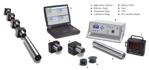
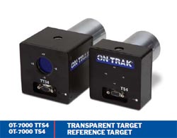
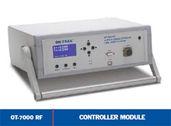
RF Spread-Spectrum Antenna. Wirelessly communicate X-Y position to the OT-7000 RF Controller Module over distances up to 300 feet.

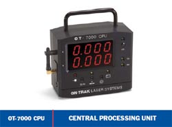
Display. Dual four-digit red LED displays make it easy to read X and Y position - even from several feet away. What's more, four levels of display brightness helps conserve battery life.

Data Averaging. Average position data from 0.25 to 5 seconds.

Zero Offset Adjust. Instantly set the zero at any point on the detector other than the mechanical/electrical zero.

Power. The internal rechargeable NiMH battery pack provides 14 to 16 hours of continuous use, depending on user-selected LED brightness. You can also power the system with the standard AC wall charger (which simultaneously recharges the batteries). A yellow LED flashes continuously when the batteries are low.

Sleep Mode. This user-selectable, battery-saving feature automatically shuts off the CPU after ten minutes of inactivity (ie., laser pulse, key entry or serial port activity). All current settings are saved.

ot7000-i

Laser Indicator. A red LED illuminates continuously while the laser strikes the detector.

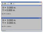
BEAM-TRAK 7000 Software. Simple-yet powerful software enables you view X-Y deviation of all targets simultaneously and in real-time. Select measurement units, set resolution, and data log position data.

ot7000-g

Wireless Communication. RF spread-spectrum (902-928 MHz) capability enables wireless data collection from remote CPUs-at distances to 300 feet.

ot7000-h
Rear View

Auto Centering. Maintains laser center on reference target. The controller module continuously polls the reference target for position data via the RF communication link. If the laser is off center, the controller communicates with internal motion controllers within the laser head that automatically realign the laser to the reference target center.

Programmable Auto-align Settings. Adjust maximum deviation at reference target and feedback sampling rates. Store these values into memory for future recall.

USB/Serial Communication. Transmit collected data via the module's USB or RS-232 communications port to your Windows-based computer. Then, perform a variety of data processing routines with Beam-Trak 7000 software.

OT-7000 System Specifications


OT-7000 LL Ultralign Laser

Power Output Class IIA (<1 mW visible red)

Wavelength 635 nm

Beam Diameter 8 to 12 mm

Beam Profile Circular gaussian, TEM00

Modulation Frequency 500 Hz

Operating Distance 0 to 300 feet (100 m)

Centering ± 0.002 inches (0.05 mm)

Weight 8 lbs. (3.64 kg.)

Overall Length 14.5 inches (368.3 mm)

Enclosure NAS standard 2.2498 inches

 (57.15 mm) diameter

OT-7000 TTS4 Transparent Target

Position Sensing Area 25 mm diameter

Resolution 0.001 inches (0.01 mm)

Centering ± 0.002 inches (0.05 mm)

 to NAS mount

Weight 2.75 lbs. (1.25 kg.)

Size NAS mount: 2.2498" x 3.0"

 (57.15 x 76 mm)

 Housing: 3.5" x 3.5" x 3.1"

 (89 x 89 x 78 mm)

Laser Acquisition Indicator Red LED flashes simultaneously with laser pulse

OT-7000 CPU Central Processing Unit

Resolution 0.001 inches

Power Rechargeable NiMH batteries

  DC wall charger

Battery Life 14-16 hours, depends on

 brightness

Display LED ± 4 digit, programmable

Weight 4 lbs.

Dimensions 6 x 5 x 2.7 inches

  (152 x 127 x 68 mm)

OT-7000 TS4 Reference Target

Position Sensing Area 25 mm diameter

Resolution 0.001 inches (0.01 mm)

Centering ± 0.002 inches (0.05 mm)

 to NAS mount

Weight 2 lbs. (0.9 kg.)

Size NAS mount: 2.2498" x 2.75"

 (57.15 x 76 mm)

 Housing: 3.5" x 3.5" x 1.6"

 (89 x 89 x 40 mm)

Laser Acquisition Indicator Red LED flashes simultaneously with laser pulse

Laser radiation. Do not stare into beam view directly with optical instruments. Viewing the laser output with certain optical instruments such as binoculars or telescopes may pose an eye hazard.

Laser Warning Hazard Label